Moving your first drop
This tutorial walks through some important steps to make sure your purpledrop is setup correctly and that you are able to move drops, and includes a video demonstrating the process at the end.
Preparation
Follow the steps in Top Plate Preparation and Mylar Film Dielectric Carrier Assembly to create a hydrophobically coated top plate and dielectric film.
Make sure your hardware is setup, and you’ve installed the driver software. You need to be ready to run the pdserver (and, optionally, pdcam) daemon either on a raspberry PI or on another computer connected via USB to your PurpleDrop. These instructions use the Dashboard UI and a web browser to control the PurpleDrop.
Switch the HV enable switch to the OFF position while setting up.
Preparing electrical connection
The top plate is driven by one of the HV507 high voltage outputs, just like the other electrodes. An electrical connection must be made to the top plate. Typically, the electrode board will provide a solderable pad or connector for this connection. This can then be attached to the copper tape on the electrode board by either soldering directly to the copper tape, or by using a cover with an electrically conductive gasket.
Note
If soldering a wire onto the copper tape, you should use a thin, flexible wire – e.g. 34 or 36AWG enamel wire – to minimize the force applied by the wire to the top plate.

Examples of top plate connection on electrode board
Installing the film and top plate
Clean the electrode board surface
Apply a thin coat of oil, such as silicone fluid or mineral oil, across the electrode board
Place the mylar film holder over the electrode board, careful to ensure that no air bubbles are trapped in the active area of the electrode board.
Place the top plate onto the mylar with spacers in between to maintain the proper gap.
Connect the top-plate to the electrode board.
Reagents
DMF devices can work with a variety of reagents, but some better than others. At MISL, most of our testing involves aqueous solutions, e.g. containing DNA.
The paper “Droplet-based microfluidics with nonaqueous solvents and solutions” tests a variety of reagents for their ability to move on a DMF, and is a good starting point if you are thinking of using different reagents.
Surfactant Additives
It is usually beneficial to mix a bit of surfactant into your solutions before placing them onto the DMF. A 0.03% concentration of Tween 20 added to a water drop helps reduce surface tension. If the drop contains suspended molecules, or magnetic beads, or if you are trying to move drops from the edge of the top plate underneath, the surfactant is likely necessary.
Place the drop onto the surface
Lift the top plate – being careful not to touch the active hydrophobic area – and pipette a small drop onto the main grid. The volume will depend on the height of the gap between top-plate and electrodes, as well as the size of the electrodes. For 0.25mm gap, and 2.5mm electrodes, start with about 4uL. For this testing, it’s not critical; as long as the volume is large enough to cover more than 1 electrode worth of area, and small enough to have some room to move around it will work. Drop volumes which cover at least 2 electrodes worth of area give the most reliable results.
Check parameters
Open up the PurpleDrop dashboard by pointing your browser at the pd-server web server on port 7000: http://<your-pd-server-ip>:7000/.
In the top-left, click the parameters button, and this will open up a dialog with a list of parameters. Here, you should check the “Enable Top Plate Augment FET” option, and set the “HV Voltage Setting” to the desired drive voltage. This can be any value in the range of 60V-300V, and the ideal value may vary depending on your setup. For the 6um mylar film dielectric, a voltage of 150V is a good place to start. In general, you want to use the lowest voltage that is sufficient, as higher voltages can decrease the lifetime of the hydrophobic surface or cause dielectric failures.
Once you’ve edited and saved the parameters, click the “Save to Flash” button at the top or else your changes will be lost after power cycling.
Note
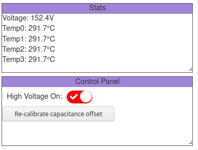
It’s possible to develop short circuits, possibly due to dielectric failure or debri on the board. Excess current draw will typically result in a decrease in the output voltage, so keep an eye on the voltage display on the dashboard while operating. If you see it drop from the nominal voltage by more than 5V or so, that may be a sign of something going wrong.
Turn on the HV supply
To enable the high voltage output, move the toggle switch on the board to the ON position, and make sure the software enable switch is ON in the dashboard. You should see the reported voltage increase to your setting, and the HV enable switch is illuminated red.
Check for capacitance measurement
Now that the high voltage is enabled, you should be able to see your drop on the capacitance panel. The exact value of the capacitance will vary with liquid, dielectric, and electrode geometry. For a 2.5x2.5mm square electrode, with 6um mylar dielectric, completely covered by water it should read something around 9pF.
In any case, you should get a substantially higher capacitance on a covered electrode than the noise read on an uncovered electrode. If you don’t get capacitance readings, this is a sign that something is not working correctly. Some things to double check:
Check that the HV output jumper is shorted
Check that the top-plate is connected
Check that your electrode board is properly seated
Check that you have the correct top plate pin steering resistors installed
Move a Drop
You can enable electrodes by clicking on them in the “Live View” panel. If you want to enable multiple electrodes at once, you can increase the brush size using the “larger” and “smaller” buttons at the bottom of the live view panel. Additionally:
Shift-click will add the clicked electrodes to the currently enabled ones
Ctrl-click will disable the clicked electrodes, leaving any other currently enabled electrodes active
Arrow keys will move the activated electrodes, so you can move a drop with them
If the drop doesn’t move, first double check that you are getting capacitance measurements. If you are measuring an increased capacitance on electrodes which are covered by the drop, this is a very good indicator that everything is wired correctly and you are in fact charging the electrodes to the expected voltage, and you can begin to ask why the electric field is not having the desired affect on the drop. If you are not, this likely suggests you have a wiring problem, or some other issue which is preventing you from driving the electrode correctly, and you can focus on debugging your electrical setup. In the former case, it may simply be a bad hydrophobic surface. You can try manually moving the drop to a different area of the board, and see if that makes any difference; often local defects in the surface create small hydrophilic areas which capture drops.