Capacitance Measurement
PurpleDrop supports capacitance sensing which can be used to detect the presence and volume of drops on the electrode array, and this information can then be used as feedback for control of the device.
What is Measured
The embedded software on PurpleDrop provides capacitance measurement in two forms: the “active” capacitance and the “scan” capacitance. The active capacitance is measured every time the activated electrodes are charged at 500Hz. This value gives the total capacitance of all currently active electrodes.
Every 500ms, the PurpleDrop briefly disables the active electrodes and performs a scan of all electrodes, activating each in sequence and measuring its capacitance. This yields an array of 128 values, each representing the capacitance measured on a single electrode.
In the future, additional modes are envisioned in which multiple regions can be defined and measured at high frequencies in order to support features such as feedback controlled drop splitting to regulate volume.
How Capacitance is Measured
The PurpleDrop uses a “coulomb counting” method of capacitance measurement, integrating the current to determine the total charge transferred. This method was chosen – instead of, for example, an AC impedance measurement – because it integrates easily with the digital outputs of the HV507 high voltage driver. It has the added benefit of effectively hiding parasitic capacitances from the measurement, as it is measuring the charge transfer between two steady states (i.e. electrodes uncharged, and electrodes completely charged and stable).
In order to achieve an alternating voltage on the device, the PurpleDrop swaps the polarity of the HV507 outputs at 500Hz. Rather than being connected to ground, the top-plate is connected to one of the 128 high voltage output pins. To apply a positive voltage, the top-plate pin – along with all inactive pins – is driven low and active pins are driven high. To apply a negative voltage, the top-plate is driven high along with all inactive pins and the active pins are driven low.

Figure 1
A sense resistor is placed in series with the top-plate output pin to measure the top-plate current. The voltage across the sense resistor is integrated with an op-amp integrator circuit. The microcontroller uses its ADC to measure the output of the integrator before switching a set of electrodes, and again after they have been charged and all transient currents have settled. The measurement gives the total charge transferred Q, and the capacitance is simply C = Q / V_HV.
Current Integration
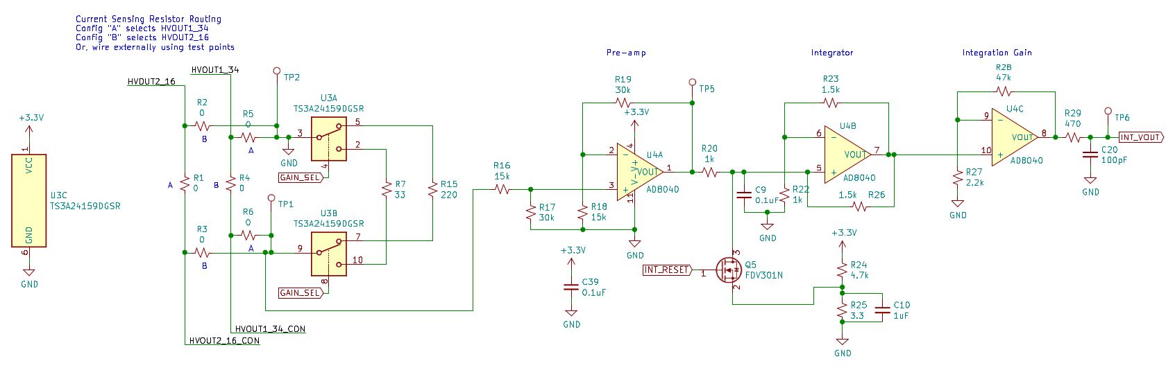
Figure 2
The integrator circuit consists of three opamps:
A pre-amp stage to provide a high-impedance input
A Deboo Integrator, which integrates the voltage input by storing charge on C9
An output gain that scales the relatively small integrator output voltage to a reasonable range for the ADC.
A FET (Q5) allows the microcontroller to discharge the integrator capacitor in preparation for a new integration. This FET discharges the capacitor to a small voltage instead of to ground in order to avoid saturating the integrator opamp output and triggering a recovery delay.
U3 is an analog mux used to select between one of two current sense resistors to provide two gain levels. The low gain level is used for measuring larger capacitances, which can occur when activating many electrodes concurrently or when activating electrodes with large areas such as reservoirs.
R2 through R6 are steering resistors which allow the current sense circuit to be connected to different pins of the HV507, or to testpoints.
The integrator has a constant ramp voltage, even when when input is 0V, due to the small offset of the pre-amp stage. This offset can be calibrated for easily, but it does lower the headroom for capacitance measurement.
Handling Large Common-Mode Voltage
One of the first issues to arise when connecting the sense resistor to the integrator is the very large common mode swing on the sense resistor. The PurpleDrop high voltage supply can go as high as 300V, which would easily damage the opamp. The solution to this is to isolate the high voltage supply from the main circuitry, and to tie the opamp ground to the top-plate output on the HV507. This means that the top-plate will stay at 0V, and the isolated high voltage ground will float to -300V when the top-plate is driven high. The PurpleDrop board was designed to minimize parasitic capacitance bewtween the isolated ground and main ground domains, as this capacitance will have to be charged and discharged on every polarity switch by a single pin of the HV507, and we’ve seen that too large of a load capacitance can damage the HV507.
Measurement Sequencing
The capacitance measurement is always made while driving the electrode high and holding the top-plate low. When switching polarity, there are substantial transient currents, even for electrodes which are inactive. Consider the case of an inactive electrode during polarity switching: It is switched at the same time as the top plate, and so in principle no voltage should be created across the device. However, the inactive electrode driver has parasitic capacitances (e.g. from traces and from the IO pad itself) which must be charged, and is not perfectly matched to the top plate output – especially considering the potential for difference in capacitive load – so they will not slew at the same rate.
The result of all of this is that these “parasitic” currents vastly exceed the signal we are trying to measure, so we need to first bring everything to a steady state and then charge only the electrode(s) that we wish to measure. Fortunately, the HV507 has BLANK and POLARITY features that make this easy to do. The POL (polarity) pin on the HV507 inverts the sense of all outputs, and the BL (blank) pin causes all outputs to go to the inactive state (it is equivalent to writing all zeros to the shift register, without having to transfer the whole shift register).
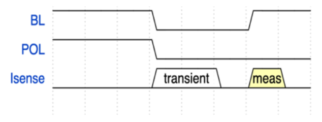
Figure 3: HV507 timing sequence during capacitance measurement
Asserting the blanking pin during the polarity switch allows all outputs to stabilize, and when it is released, the active outputs only are driven high together. Figure 4 shows two oscilloscope captures, the first without a drop present and the second with a drop covering the electrode being measured.
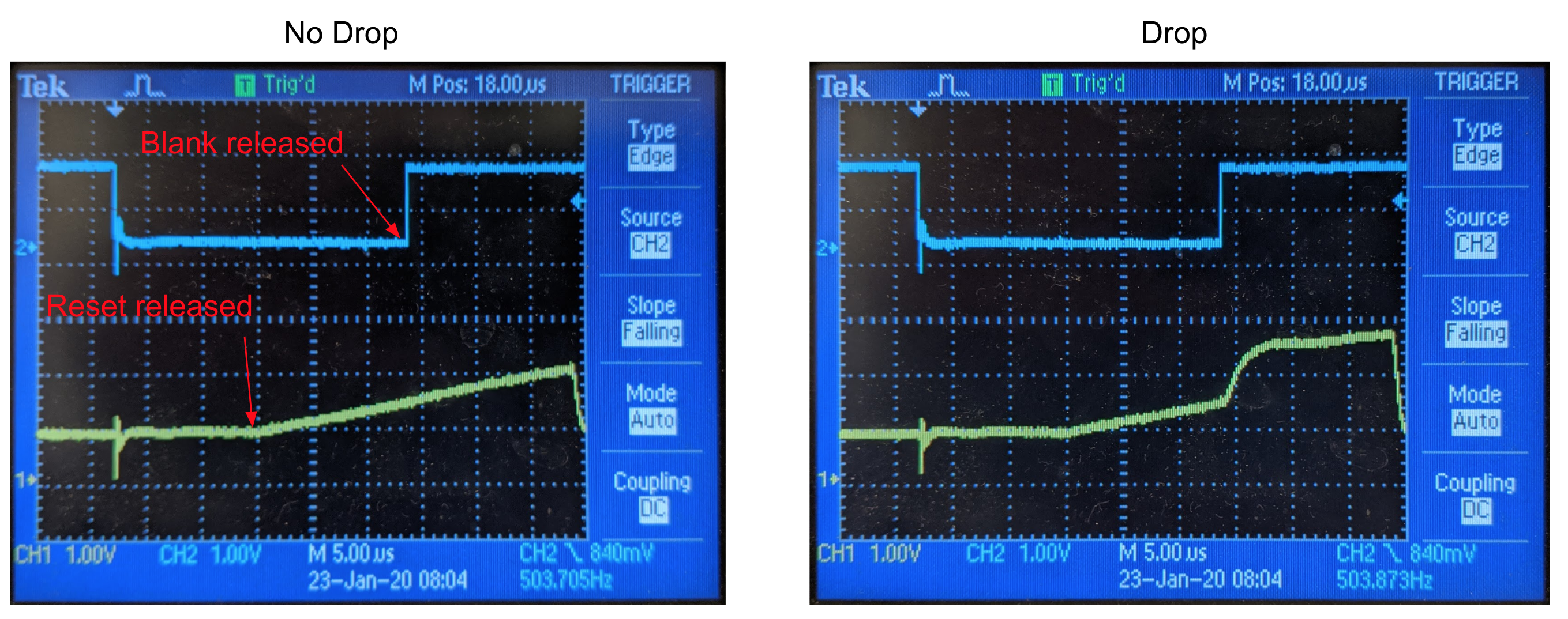
Figure 4: Note that integration time shown is longer than actual implementation
Current Integration Times
For a typical electrode, the maximum capacitance (when fully covered by a drop) is around 10pF, and a current integration time of 10us is sufficient. However, for larger electrodes, the integration time may need to be increased. The electrode board definition file allows for a subset of the electrodes to be designated as “large”, and for these electrodes the lower gain setting is used, along with a longer integration time. Both the high-gain and low-gain integration times are configurable parameters, which can be adjusted from the Parameters form on the UI.
Noise and Low-side Augmentation
Rev 6 of the PurpleDrop hardware suffered from significant noise in the capacitance measurement caused by the switching of the high voltage regulator, which induces a current through the sense resistor. Although these current pulses are brief and essentially zero-mean, they still show up as a non-zero-mean error signal in the integrator output, as the integrator cannot integrate the negative part of the current ripple. This problem is rooted in the fact that the HV507 output has a fairly high impedance, and it was solved by adding an additional FET to augment the low-side of the top plate pin on the HV507, which helps to drive the main GND to the isolated REFGND net during current sensing.
This “augment” FET will be included on future revisions of the board design, but it should be added to a rev6 board when accurate capacitance measurement is needed.
Sources of Error
It seems clear that the primary source of error is not in measuring the charge transfer, but in relating the charge transfer to the volume of fluid covering the electrode. The two main sources of error appear to stem from geometric concerns and dielelectric properties.
Computing Volume
As long as the fluid being used is somewhat conductive, we we can assume that all of the voltage drop will be across the dielectric and the fluid itself will have no drop once steady state is reached. This means that the capacitance will be proportional to the area covered by the drop, and volume is the product of the area covered and the gap height between the electrodes and top plate.
It is possible to measure this height, but some error can creep in if, for example, the top plate is mounted at slight angle so that the gap is not constant.
Dielectric Hysteresis
The current integration does a good job of measuring capacitance if we define it as the amount of charge transferred to raise the electrode voltage from 0V to V_HV. However, physics has some wrenches to throw still. Our capacitor is not ideal, and the amount of charge required to do this may not be constant. In fact, it can depend on the previous state of the dielectric. The first challenge that presented itself when testing capacitance sensing was that the measured capacitance was found to depend on whether an electrode was previously activated before measurement, and on how long it had been since it was last charged to a negative voltage.
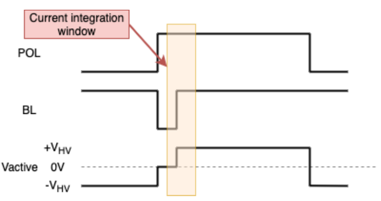
Figure 5: Timing diagram illustrating the “active” capacitance measurement
During active capacitance measurement (figure 5), the charge transfer is measured from 0V to +V_HV volts. However, in all measurements the dielectric was charged to -V_HV a short and constant time before the current measurement.

Figure 6: Timing diagram illustrating the “scan” capacitance measurement
During the capacitance scan (figure 6) the dielectric covering the electrode being measured may have been recently charged negatively, or it may not have, depending on whether the electrode is active. Even among active electrodes, the time elapsed since being charged negatively varies based on the electrode number (pin 127 is measured first, pin 0 is measured last). The time between the first and last measurement can vary depending on integration time and blanking settings, but it is typically on the order of 2ms.
The amount of hysteresis depends on the material and the temperature. Kapton film dielectrics have been found to have extreme hysteresis, with the measured capacitance more than doubling when the dielectric is driven negatively (active)prior to measurement relative to not being driven negative (inactive). Mylar film has a measurable, but much less pronounched increase of approximately 15% at room temperature, but it has been found to increase at higher temperatures.
A detailed exploration of the material properties is a full topic on its own. Here, the main takeaway for operating PurpleDrop is that the scan capacitance is useful for determining the presence of drops on the board, but for the most accurate volume estimate the active capacitance should be preferred.
Accessing the Capacitance Measurements in Software
There are two RPC calls available to access the two modes of capacitance measurement.
The active_capacitance method returns the latest value for active electrodes.
The bulk_capacitance method returns the latest scan value.
Note that for both of these methods, they return the latest value available when called. This is not much of a concern for active_capacitance, as it is updated very frequently (500Hz). But for bulk_capacitance, the reading may be up to 0.5 seconds out-of-date, and you may need to take this into consideration when writing your code.