Setting Up and Powering the PurpleDrop
Before you power up
Warning
The PurpleDrop is a high voltage device and must be treated with care. The high voltage is enabled by throwing the toggle switch on the board to the HV_ON position. The switch will be illuminated when the high voltage is on, as a reminder. You must be cautious handling the purpledrop when the high voltage is on as it can shock you if you touch the wrong conductors – and there are many high voltage nets on the board. When you need to handle the device, e.g. to adjust or replace the top plate, first switch off the high voltage.
Selecting the top-plate output pin
Make sure the purpledrop has the correct top plate pin enabled before energizing the electrodes.
One of the HV507 high voltage outputs is used to drive the top-plate, and this pin is connected to additional circuitry for current sensing. Steering resistors (R1-R6) can be used to choose between three options for this pin:
Config A (R1, R5, R6) selects pin 97 (default, used with most electrode boards and recommended for new designs)
Config B (R2, R3, R4) selects pin 15 (used with electrode board v3)
Config C (R1, R4) wires the current sense only to test points for external wiring
Only one set of resistors should be populated, and config A is the “standard” option. You should only need to change from config A if you are using a v3 electrode board, or have reviewed the schematic and know what you’re doing. There is also a software configuration setting named “Top Plate Pin”, which controls which pin is driven as the top plate; this must be set to match the installed resistors.
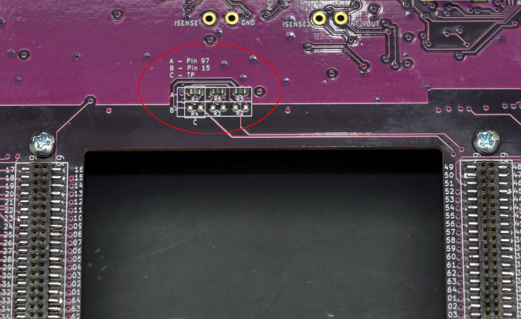
Shorting (0 ohm) resistors used on the purpledrop to select which pin is connected to the top-plate capacitance sensing circuitry.
Warning
It’s critical to ensure that software setting matches the hardware configuration before turning on the high voltage, as an incorrect setting can lead to a short circuit on the top-plate output.
Note
Note that on rev. 6.0 of the PurpleDrop (fixed in 6.1) the silkscreen incorrectly labels config A as pin 93
Note
Pin 15 remains an option for backwards compatibility, but for any new electrode designs, you are encouraged to always use pin 97 to drive the top plate.
Board Standoffs
It’s recommended to install standoffs onto the main board for it to stand on. There are 8 holes in the board, sized for 2-56 screws.
This 3/4” length 2-56 standoff works well along with 1/4” long 2-56 machine screws.
Note
The “extra” mounting holes near the electrode board connectors are important to populate. Without these, installing the electrode board can cause a lot of flex in the PCB, which may lead to damage over time.
Powering the PurpleDrop
The PurpleDrop has two power inputs: The micro-USB connector and a 2.1x5.5mm barrel connector for AUX power. The AUX power is wired by diode-OR, so that when the voltage at the AUX input exceeds the USB voltage by more than about about 0.3V, it will be used as the power source. This can be useful for monitoring the power draw (e.g. on a benchtop power supply), or when high current draw is necessary (e.g. when driving heaters).
The nominal power draw of the PurpleDrop is about 100mA @ 5V, which can be readily supplied by a USB port. However, when using the heater outputs, the current draw can be up to 1.9A, which will exceed the capabilities of many USB ports. When using the heater, it is recommended to connect a 5.5 to 6V power supply to the AUX power connector.