Mylar Film Dielectric Carrier Assembly
The drops don’t sit directly on the electrodes; there is a layer in between that provides electrical isolation (dielectric) and hydrophobicity (hydrophobic coating). There are a number of options for these layers, including vapor deposited coatings. One relatively simple and easy method is to use a thin film of mylar as the dielectric, and spin on a coating to make it hydrophobic.
These instructions describe how we build a mylar film onto an FR-4 frame that keeps it rigid and allows it to be attached to the electrode board.
Supplies
FR4 frame (Custom made from PCB fab, see below)
Mylar film (TF-160 3” roll: https://www.premierlabsupply.com/product/mylar-film-6-0/)
Adhesive Transfer Tape Sheet (3M 468MP or similar)
Cytonix Fluoropel PFC1101V (https://cytonix.com/products/1101v_25grams)
Tools
Knife
Spin coater
Pipette capable of dispensing 450uL
Oven or hot plate capable of heating to 120C
Ordering the FR4 Frame
Note
These instructions include design files for a basic frame with a wide opening. There are more recent frame designs that are recommended for most purposes, which can be found at Building DMF Surfaces. The instructions for how to prepare the frame remain the same for these other designs.
The frame itself is made from FR4. The primary considerations for the material are that it can survive the baking of the hydrophobic coating and a sufficiently low coefficient of thermal expansion so that it doesn’t over stretch the mylar while heating, either causing tearing or a failure of the adhesive. For this reasons, many options – such as laser cut acrylic, or 3D printed ABS – will not perform well for this task. The frame can be ordered cheaply from a prototype PCB vendor, such as Seeed Fusion, as it is essentially a PCB with no copper or other layers.
PCB vendors expect designs to be uploaded in gerber format. The gerbers for the 100x74mm frame can be found here: film_carrier_100x74_gerbers.zip

Video Instructions
Assembly Procedure
1. Apply adhesive to frame
Cut a rectangle out of the adhesive sheet, large enough to cover the frame with a bit of extra margin.
Clean the surface of the frame to be adhered, e.g. with some IPA and kim wipes.
Peel one side of the adhesive backing off of the adhesive, and lay it down sticky side up. It may be useful here to use a scrap peice of the adhesive backing for holding down one corner while you peel.
Place the frame down onto the adhesive, and press firmly.
Using a knife and a cutting mat, cut away the excess adhesive film in the center and around the edges of the frame.
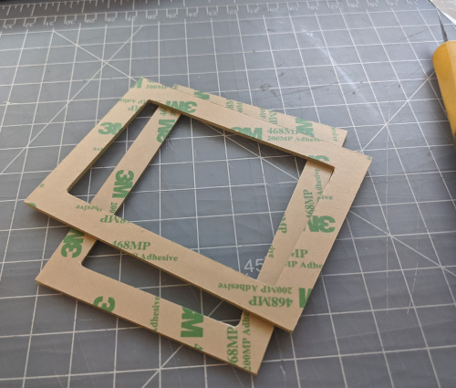
Frames with adhesive applied
2. Apply mylar film to frame
Cut a length of the mylar film, approximately 8” (not critical, just enough to cover the frame with plenty of extra).
Lay the mylar out on a clean work surface, and tape the four corners to the table such that the film is stretched out flat with minimal wrinkles.
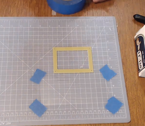
Mylar film taped out ready for adhesive back frame to be applied
Peel the adhesive backing from the frame, and place it down onto the mylar, careful to center it so that the mylar covers the entire frame.
Using a knife, cut away the excess mylar from around the outer edge of the frame.
3. Preheat the frame to shrink the mylar
After attaching the mylar, it may have a bit of slack in it. Heat the assembly at 100-120C for a few minutes using an oven or hotplate to shrink the mylar. After baking, the film should be tight and flat.
4. Spin-on hydrophobic coating
Place the frame in a spin coater. If your spin coater has a vacuum chuck, you may need to tape the frame onto a carrier – a 6” petri dish works for this – to install it onto the chuck.
Spin at 1000RPM, and apply ~450uL of Fluropel FPC1101V in the center using a pipette. Allow to spin for 30 seconds after application.
5. Bake coating
Use an oven or hot plate to heat the frame/film to 120C for 30 minutes to evaporate solvent.
6. Frame installation
Using a knife, puncture the film at the four screw holes in the frame to allow a screw to pass.
Clean the electrode board to remove any debri, and spread a thin layer of 2.0cst silicone fluid onto the electrode board by brushing with a kim wipe, foam brush, or similar.
Place the frame down onto the electrode board, and secure to the PCB with four 2-56 screws.